
SolidWorks
Click on each project to view in detail.
Hold Ctrl and scroll to zoom.
 LiDAR Drone (2019) |  Predator Drone (2018) |  Self-Inflating Tent (2020) |
|---|---|---|
 V6 Engine Assembly (2021) |  Butterfly Valve Assembly (2020) |  (2021) |
 Nvidia GeForce RTX 2080 (2021) |  Rotor Assembly (2021) |  Mecanum Wheel (2021) |
 Fender Stratocaster (2021) |  Bosch Hydraulic Pump (2021) |  Car Wheel (2019) |
 Idler Arm (2019) |  Landing Gear Assembly (2019) |  UDF Rotor (2019) |
 Screwdriver Handle (2019) |  Jensen Mechanism (2019) |  Bicycle Chain (2019) |
Quadcopter Drone
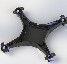
Lower Shell of Drone Body
The lower shell supports the PCB, wiring and the motors of the quadcopter drone. The PCB is fitted into the square slot in the middle and screwed to the shell to prevent it from getting damaged. The wires travel along the arms of the shell to a DC motor at each end. The small holes at the center allow for the LED to protrude out as indicators for the front and back side of the drone body.

Upper Shell of Drone Body
The upper shell of the drone body screws onto the lower shell and encases all the inner components safely inside to form the drone body. The shells are made of ABS plastic which makes it very durable and crack-resistant.

Propeller
This double-bladed propeller is one of four propellers, for each motor of the quadcopter. It is made of ABS polycarbonate, which makes it sturdy enough to rotate at 10,500 rpm and generate enough lift for the quadcopter to take flight. The sweep angle of the fins allow air to flow downwards, creating thrust.

Landing Gear, Propeller Guards, Camera Mount and Battery Slot
The landing gear of the drone is made of tough TPU, which allows it to absorb shock upon landing, instead of causing fractures. The propeller guards protect the sensitive parts of the quadcopter, such as the motors, propellers and electronics from impacts. The camera is mounted on a thin swivel, which is screwed to the bottom of the lower shell along with the battery slot.

Predator Drone
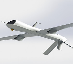
Drone Body
The drone body is designed to be aerodynamic, by sweep extruding two splines for the top and bottom edges. The airfoil of the wings is created by sweeping through data points taken from the UIUC clarky's airfoil website.
Missile Launcher
The missile launcher is designed to be installed to the drone's wings, by the two extrusions on top. Each launcher has two rails at the bottom which hold two Hellfire missiles.

Propeller
The propeller has 3 blades that is designed with symmetric sweep angles and an airfoil similar to the wings. Since the propeller attaches to the end of the drone on a rotating shaft, the airfoil pushes air to propel the drone forwards.

Hellfire Missile
The Hellfire missile design is adopted from the actual designs, with four fins that streamline the missile and two hooks that latch onto the launcher rails. These hooks detach when the missile is prepped to launch.
Self-Inflating Tent

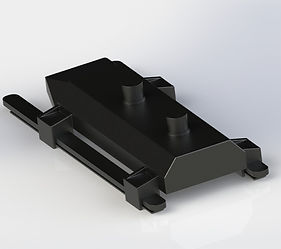
Base Floor
The base floor is made of polyurethane with polystyrene lining, which makes it water-resistant and airtight. The U-shaped bladder on top fills up with air, along with the base floor, similar to an air mattress. This makes the base floor extra comfortable for campers.
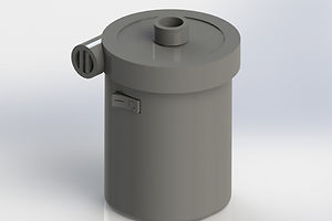
Rechargeable DC Air Pump
This air pump is fully battery-powered and rechargeable. It has a suction valve at the top which forces air through the compressor to the outlet valve. The air pump operates at 0.44 PSL air pressure and is sufficient enough to inflate the base floor in 2-3 minutes.

Rod Assembly
The rod assemblies supporting the canvas of the tent composes of aluminum hollow rods that slide within one another. This allows it to collapse and expand according to the height of the U-Bladder when inflating. The rod socket at the bottom is shelled out and is made of ABS plastic to bear the stress of the weight of the rod assembly and canvas. Each of the rods have an ring extrusion at each end which locks the rods when they reach the end of their lengths during expansion.

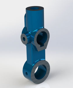
Rod Connector
The rod connector is integral to this system because it connects two rod assemblies that expand from either side of the tent's base floor. The rod passed through the holes and the spring-loaded locking mechanism at the end locks them into place when they reach the end of their length.

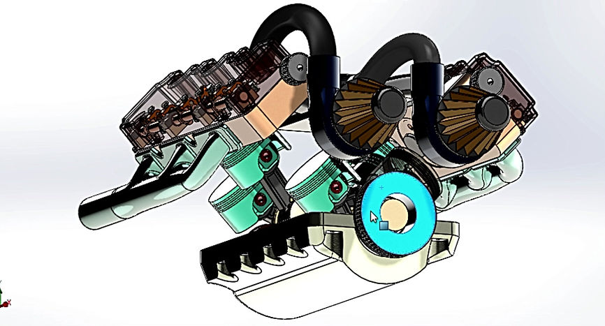
V6 Engine Assembly

Piston Assembly
The piston assembly consists of the piston head, which is connected to the piston rod with a rod. The piston cap (yellow) keeps the piston assembly attached to the crankshaft.

Rocker Arm Assembly
The rocker arm assembly consists of a rocker arm with 1 DOF that allows it to tilt back and forth. The two rollers at each end allow the arm to tilt when the rotating cams pass under them. A hex bolt holds down the rocker arm to the cylinder head.

Engine Block
The engine block is made of cast steel. It holds the primary components: the crankshaft in the center, piston assemblies in the cylinders and the oil pan underneath.

Crankshaft
The crankshaft holds the piston assemblies. Each arm is 120 degrees rotated away from one another and holds two piston assemblies. This allows a sequential motion of the piston heads sliding up and down the cylinders (as one goes up, the farther one comes down).

Intake Manifold
The intake manifold supplies an air-fuel mixture to the cylinders, where the piston heads move. It also helps cool down the engine to prevent it from overheating.

Cylinder Head
The cylinder head protects the piston assemblies and contains the valve assemblies which move up and down with the rocker arms. The cam shaft is held down by brackets on the flip side of this cylinder head, where it rotates.

Cam Shaft
The cam shaft rotates on the upper side of the cylinder head. The cams are fixed and as the shaft rotates, each cam pushes down on the valve springs.

Engine Belt Wheel
The engine belt wheel rotates the cam shaft. Two belts connect the two cam shaft wheels to the crankshaft wheel.
Butterfly Valve Assembly

Butterfly Housing
This particular butterfly valve housing allows air to flow through for an internal combustion engine to achieve excess air intake. The flange is attached to a supercharger for increased air intake into the intake manifold.

Butterfly Shaft
This butterfly disc is installed into the shaft using two steel rivets. The shaft has a keyhole where a woodruff key fits into. As the accelerator pedal is pressed, this shaft rotates, making the disc rotate, allowing air to be forced in.

Pinion Gear 16 DP 14T 0.625FW
The pinion gear is part of a standard rack and pinion mechanism, with a diametral pitch of 16, 14 teeth and 0.625 face width. The woodruff key is turned by the keyhole on this gear.
Rack
This rack gear shifts back and forth as the accelerator of the car is pressed. The pinion gear rolls along this linear rack gear to convert translational motion into rotational motion.
Rack Housing
The rack housing encases the rack and pinion gear mechanism, protecting it from external forces and therefore, damage. It is connected to the butterfly housing with machine screws.

Steel Rivet
These steel rivets are used to attach the butterfly disc to the butterfly shaft. The cold-rolled steel used to manufacture these rivets make them extremely resistant to wear and tear, and corrosion.

Key Screw
This key screw is inserted beneath the rack housing. Turning this screw allows the rack to slide and therefore allowing the butterfly shaft to rotate when the accelerator is pressed.

Machine Screw
These round head machine screws are used to hold the entire assembly together, using the rack and butterfly housings.


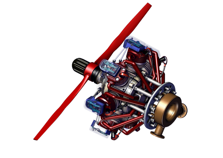
Radial Engine

Cylinder Head Assembly
The cylinder head assembly consists of a base casket, cylinder liner, the cylinder head (red) which encases the valve assembly. The brackets (blue) encase the rocker arms and rods which protrude out from behind the cylinders. The ignition plug allows air-fuel mixture to enter the cylinders.
Cam and Wheel Assembly
The cam and wheel assembly consists of two cams: front (green) and rear (blue), and a hollow wheel (yellow) that allows the cams to rotate as the planet wheels on the piston shaft head rotates.

Rocker and Valve Assembly
The rocker and valve assembly consists of two rocker arms connected to their individual rod and pound. As the cam rotates, the rocker arm presses down on the valve springs. The spark plug is shown inside the ignition plug (shown transparent).
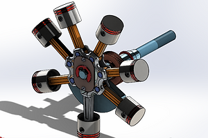
Piston-Shaft Assembly
The piston-shaft assembly consists of the piston shaft that holds the sun wheel behind the piston and connecting rod assembly. A lock washer holds the front plate in place which prevents the main connecting rod from coming loose.

Cam Housing Assembly
The cam housing consists of the cam housing which has holes for the rod of the rocker arms to move through. Ram bearings prevent the rod from sliding out with the help of a pounds. A roller bearing in the center prevents it from rotating along with the crankshaft.
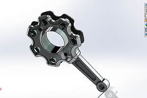
Main Connecting Rod
The main connecting rod of the piston-shaft assembly has holes through which the piston axles connect the piston assemblies to. The rod moves in a circular motion as the shaft turns, which creates the sequential motion of the pistons.

Cylinder Head
The cylinder head encases the valve cylinders. On top, the rocker arms are attached inside a bracket cover. The center holes are for the valves and the corner holes are to attach the head to the cylinder liner with steel hex-head bolts.
Intake Pipe Assembly
The intake pipe assembly is constructed with a sweep base on a 3D sketch, from the fixed mouth all the way to the pipe union and ring at the bottom. The mouth is connected to the cylinders with a flange seal and the bottom connects to the exhaust collector at the back of the engine.

Nvidia GeForce RTX 2080

Dissipater
The GPU dissipater encases the PCB and serves to dissipate the heat generated. The GeForce RTX 2080 has 2 cooler fans installed above and 132 radiator fins in a linear pattern below the fans.
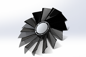
Fan
There are 2 cooler fans. The fins are crated by loft extruding two sketches and lastly, extruding it to the surface of the flywheel.

Support Bracket
This support bracket holds the GPU dissipater to the CPU casing. The top row of holes are for 3 display ports and one HDMI port. The smaller holes are present to allow heat dissipation. The part is created as sheet metal and a base flange, which is bended.

Simplified PCB
This is a simplified outline of the PCB which is attached below the dissipater. The holes are to screw various electrical components on it.

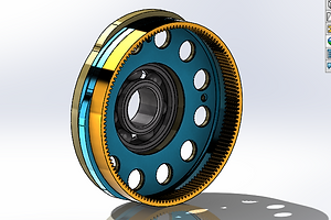
Rotor

Core Disk
These core disks are of a Y-configuration, designed for wound rotors. They provide 3-phase windings evenly spaced at 120 degrees.

Contact Holder
The contact holder holds the coil wire in each arm. It helps the wire coil around the armature of the rotor, as the shaft rotates.

Coil Wire
The copper wire coils around the armature formed by a linear pattern of the core disks. As current travels through this wire, a magnetic field is created around the core.

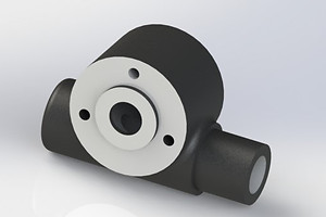
Bosch Hydraulic Pump
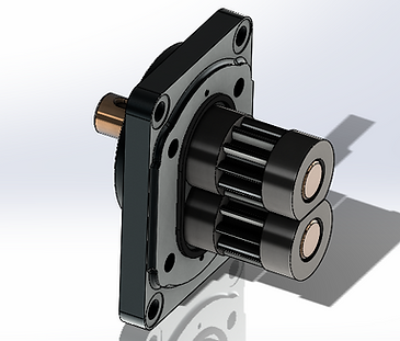
Drive Shaft and Idle Gear
The interior of the pump is as shown. The drive shaft assembly is held in place with the lag sleeves on each end. The bottom idle gear turns as the drive shaft turns.

Oil Seal
The O-ring oil seal provides adequate pressure on the shaft to prevent leakage. Most hydraulic systems require one.

Interior Assembly
The body is made transparent to view the inner assembly of the hydraulic pump. The front end plate is hidden. The body has the pump specifications inscribed on it. Two pipe nozzles protrude from each side.
Car Wheel

Tire
This 16-inch car wheel tire is designed as a revolution around an axis and cut-extruded to fit the rim inside. The threads of the tire are sketched, geometric patterned around the same axis and cut extruded.

Rim
The car rim is designed similar to the car tire (revolving around an axis) and the rim pattern is made with patterned cuts. The bolt holes around the hub are geometric patterned to create a fixture to the sprocket.

Hub Cap
The hub cap is bronze-polished to make it corrosion-resistant and attractive. The logo is embellished at front and the interior is shelled out to fit into the socket at the center of the rim.
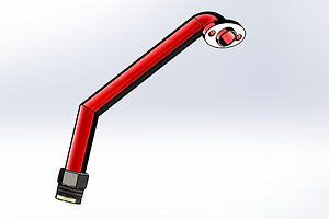
Idler Arm

Front Isotropic View
This idler arm acts as a pivoting support for the steering linkage. The front surfaces of the idler arm which connect to other components are machined and the other surfaces are galvanized for corrosion-resistance. The inner surfaces of the through-holes are also rendered frictionless for ease of rotatability.

Back Isotropic View
The back surfaces are also kept with the machine marks since they will connect to other components within the car's steering linkage mechanism. The shaft is locked into the bottom through-hole and the top hole is bolted to the car's chassis.
Landing Gear Assembly
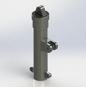
Shock Strut
This hydraulic shock strut absorbs and dissipates shock loads. This part is fixed to the aircraft and does not move. The extrusion with the holes on the cylindrical surface is

Wheel Hub
The wheel hub of the landing gear assembly serves as the holder through which the shaft supporting the wheels pass. This hub is bolted to the lower sway link. The hole at the top surface allows the piston to be fixed to the wheel hub component of the assembly.

Sway Links
These links are used to extend the piston in and out of the shock strut. One link is fixed to the strut of the assembly on one end and to another link at the other end. The second lick is connected to the bottom of the piston and this elbow joint link allows the piston to slide up and down through the fixed strut.

Piston
The piston is attached to the wheel hub of the landing gear assembly with steel bolts and nuts. The piston slides in and out of the shock strut.
Mecanum Wheel

Base Flange
The base flange is designed with a 45-degree bend of radius 1 mm and holes are created at the end of the bends, where the axle of the rollers are connected on each side to the flanges with bolts and nuts. A washer prevents the rollers from wearing out as they rotate. A shaft coupler connects the wheels to the device through the center hole.

Roller
The rollers are made of ABS plastic and have a smooth surface, which allows them to roll easily. The inset at each end of the rollers are for the washers and nuts to be inserted.
Fender Stratocaster

String Source
The string source is made of chrome-plated steel, with slots where the strings fit into the electronics inside the guitar body. It is bolted onto the guitar body.

Tone Knob
The tone knob is simply designed with a bold font and a jagged circumference that allows easy grip.

Plug
The guitar plug is inset into the guitar body, with the port for the electrical inlet jack tucked inside. This prevents it from breaking off.

Pegs and Signature
The turning pegs on the neck are used to tune the guitar. The Fender signature is auto-traced onto the neck from an image of the logo.
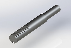
Screwdriver Handle

Handle
The handle is designed to be knurled with a criss-cross pattern, which helps increase grip strength and therefore, apply more torque to the screw head. The end is chamfered for reducing risk of injury on any sharp edges.
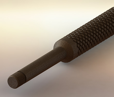
Shaft
The shaft is made to be an appropriate length and tapped with the thread pitch of the different driver heads. This allows one handle to be used for various driver heads. The entire handle is brushed brass to give it a rough surface which allows enhanced grip.
Jansen Mechanism

Motion of Jansen Mechanism
The Jansen Mechanism is a kinetic sculpture that generates a smooth walking motion. This mechanism is essential for the mainframe linkages of 4-legged robots, due to its scalable design, low payload to machine load ratio and energy efficient design.
UDF Rotor

Front View
The UDF rotor is a disc on which the brake pads clamp down on to stop the vehicle's wheels from spinning. The rotor has two discs with fins in the middle, to dissipate heat generated from friction between the rotor and brake pads. The holes allow the hot air to be expelled.

Back View
The cut extrusion through the middle is shown here, where it fits onto the wheel hub of the car. The 4 bolt holes are used to attach the rotor to the wheel hub. The holes in the back are also there for heat dissipation.
Bicycle Chain
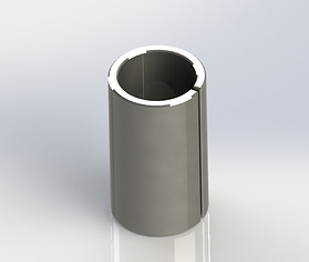
Bushing
This bushing is integrated with the inner plate of the roller link of the bicycle chain. It simply reduces friction between the roller links and the pin link when the chain is rotating. The sliver on the bushing's surface is to allow it to flex under pressure and not crack.
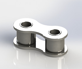
Roller Link
The roller link consists of 2 bushings encapsulated within the roller link plates. This roller link assembly is one of many that helps the chain to roll smoothly.

Pin Link
These links are used to extend the piston in and out of the shock strut. One link is fixed to the strut of the assembly on one end and to another link at the other end. The second lick is connected to the bottom of the piston and this elbow joint link allows the piston to slide up and down through the fixed strut.

Chain Assembly
The chain assembly consists of roller links and pin links. The pins are set inside the bushings where they roll in a frictionless manner, allowing the bicycle chain to roll.