top of page

Trelleborg Sealing Solutions


hose fixture
Hose Elasticity Test Fixture


Female End with Threads


Male End with Screw
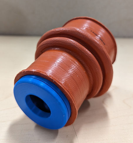
The purpose of this fixture is to determine how much the hose is able to expand and meet customer requirements. The hose is fixed to the fixture using hose clamps and the male end with the screw is rotated outwards while the female end is held steady. This forces the hose to expand outwards and meet tolerances. The male end is 3D-printed as one part including the internal screw using support material.

Section View of Assembly
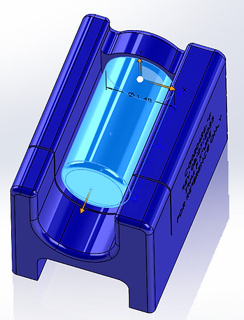
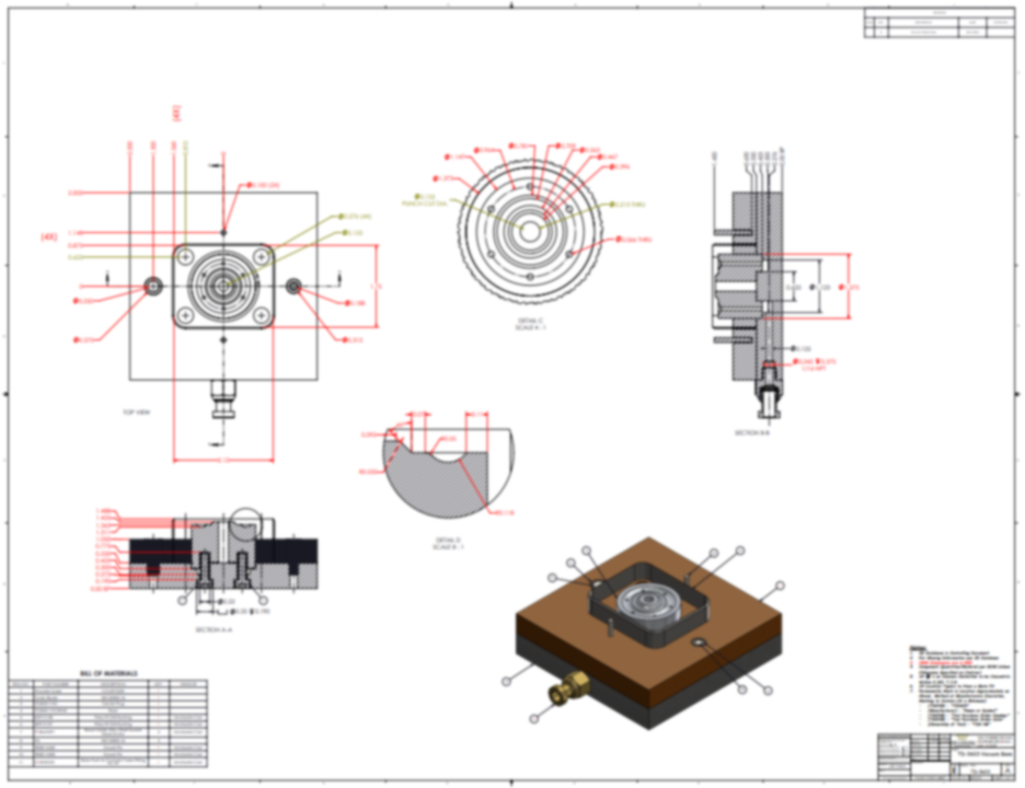
Mold tool
Diaphragm Mold Tool Design
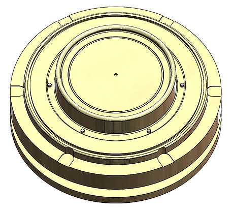
Cavity Part of Mold Tool

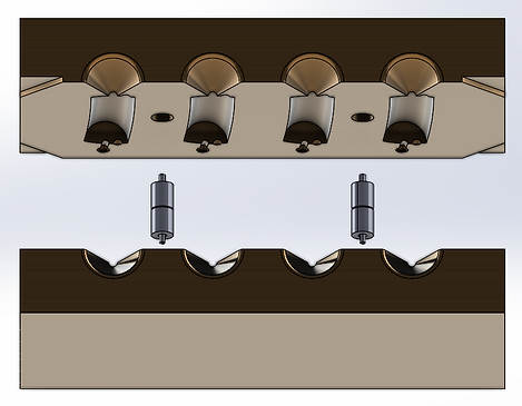
Section View of Tool Assembly

Close-up View of Core+Cavity

Section View of Diaphragm Part

Diaphragm Mold Tool Drawing
Hose template
Hose Length Template Fixture

The purpose of this fixture is to ensure that the features of the hose comes out to required specification. The part was suffering from post-cure shrinkage and a template was needed to help the operator use a specific amount of excess material to compensate for the shrinkage.
mandrel tool
Paraplast Mold Tool for Mandrels

Exploded View of Paraplast Mold Tool

Section View of Paraplast Mold Tool
The purpose of this paraplast mold tool is to form soluble paraplast mandrels that help form the shape of the airframe fire seals that resemble long hollow fabric-reinforced silicon pipes joined together in various angled elbows. The soluble mandrels are used to help retain the shape of the joints during the curing process.
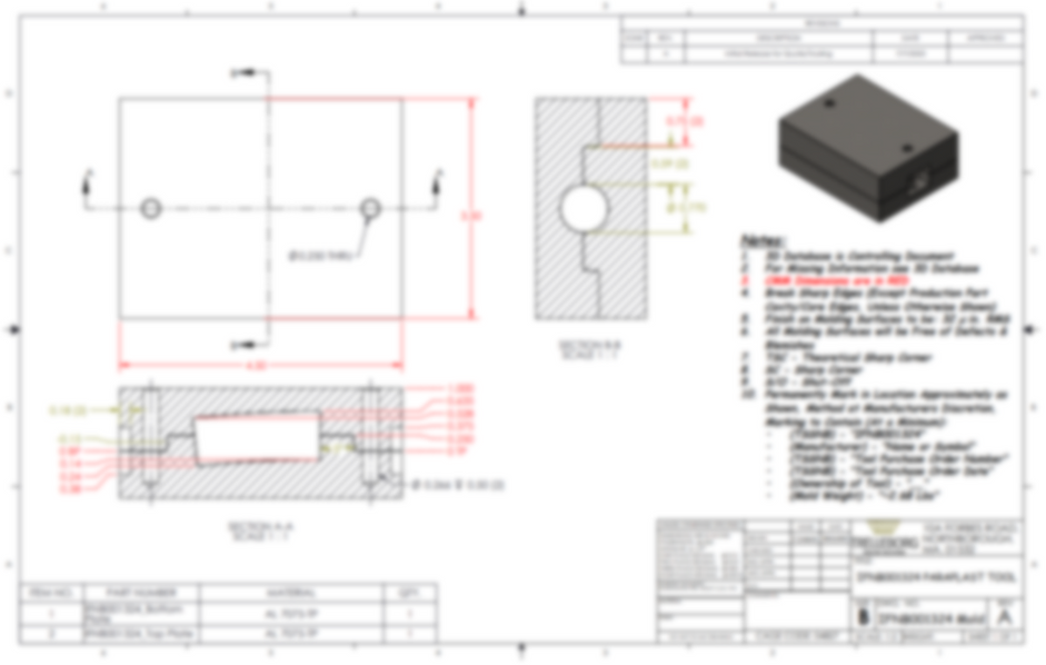
Paraplast Mold Tool Drawing - Blurred
trim fixture
Cut Fixture for Gasket


Exploded View of Trim Fixture and Part
The purpose of this trim fixture (blue and red) is to help the operator make cuts into the part using a razor blade. The fixtures are designed to have depth control for the cuts, since the cuts are exactly halfway into the gasket, stopping at the mylar layer in the middle.
cut fixture
Trim Fixture for Airframe Fire Seal

Isometric and Front View
The purpose of this cut fixture is to help the operator trim the end of long airframe fire seals (resembling hollow pipes) to meet customer specified length requirements. The highlighted cylinder is to provide support so the seal does not fold when cutting force is applied.

trim die
Trim Die for Diaphragm Layup

Exploded View of Trim Die Assembly
The purpose of this trim die is to cutaway holes from the layup material that is compression molded to form small diaphragms. The die is used in clicker presses where the outer blade (square) cuts the outer boundary and the punches make holes that fit into the mold tool. The trim die pieces are screwed from under and a vacuum piece (center) holds down the layup material for a clean punch cut.
Vacuum Trim Die Drawing - Blurred
layup template
Mylar Template for Layup on Mold

The purpose of this mylar template is to help the operator fill in the layup material easily and consistently for every batch. The two corner holes act as position control that fixes the template into the cavity part of the mold tool.
cut fix gasket
Cut Fixture for Gasket


Exploded View


Close-up View - Top and Bottom
The purpose of this cut fixture is to help the operator make cuts to the middle mylar layer of the gasket part. The gasket is positioned to the bottom fixture and held in place by the top fixture which clips to the bottom's pillars. This allows consistent cuts using a razor blade.
ActiviTEE
IIoT Platform Utilization
-
The scope of this project was to understand how well the production line of mold presses were performing, based on calculated OEE values.
-
Using machine runtime values and coded downtimes like planned and unplanned stops, operator breaks, machine layups, etc, a real-time overview of the shop floor is monitored.
-
An implementation plan is drawn out:
Implementation Plan
-
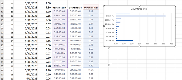
The downtimes for each press in one workstation are recorded and organized into an Excel spreadsheet for ease of comparison:
-
This is conducted over several days and a trend is noticed, which was used to code the downtimes, for example: "Machine Prep", "Employee Break", "Lunch". Anything irregular could be coded as "Machine Down" and needs to be investigated.
-
A demo of this platform is active and functional. It utilizes various methods and systems to participate in IIoT to gather machine data and convert into readable information that is extremely valuable for both engineers and management to observe and discover anomalies in the process. The platform is also integrated with the central MRP software to allow end-users to log the start and end of a manufacturing order, along with the work station, job and item numbers, target time per part, MO quantity, expected setup time and parts per cycle.
-
My project involved establishing the use of the platform at the Northborough plant; obstacles faced were the impact of sudden change and training periods for operators and end-users alike. Despite the short amount of time that I committed to this project, enough data and user guides were generated to help consecutive project members carry it forward.

floorplan
Shop Floor Layout

The floor layout for airframe seal trimming required rearranging to improve takt time. Instead of the tables facing one another, an online tool (floorplancreator.net) was used to rearrange the workstations in a linear arrangement, according to scale. This helped increase operator efficiency and reducing takt time for cycles, while utilizing the same resources.
bottom of page